"[Contest] The Talent I Am Proud Of || Season-2".
| Assalamu Alaikum |
|---|
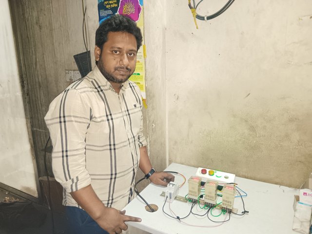
I am @saifuddinmahmud from Bangladesh. I am excited to join this contest. The contest name is The Talent I Am Proud Of. The contest organised by honorable @pea07. I am going to join this contest. I hope everyone will like my post.
Every person has some skills inside them that they want to show off. I am an electrical engineer. I am skilled in various electrical tasks. Today I will share one such technical task with my Steemian friends.
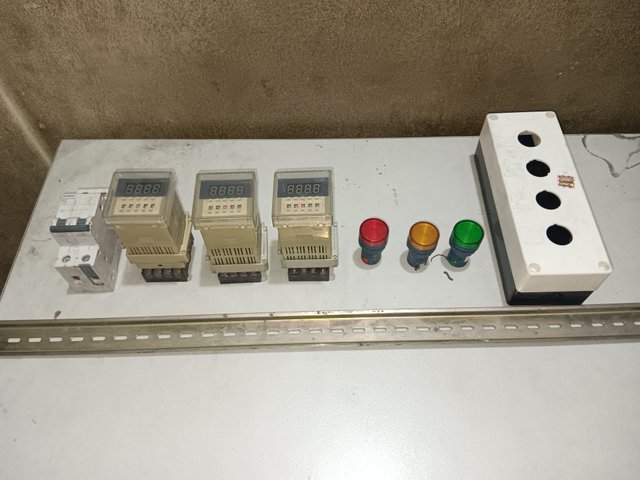
My job is to design traffic signal indicating lamps. When we drive on the road, we see red, yellow, and green lights on the signal. They turn on and off automatically after a while. I will share how this controlling is done.
Some of the things I need to do this job are-
- MCB (Miniature Circuit breaker)1 pcs
- Timer with base (3pcs)
- Indicating Lamp (3pcs)
- Control box (1pcs)
- Channel (1 pcs)
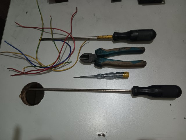
Some of the instruments i need-
- Some pieces of cable
- Star screw driver.
- Flat screw dplayers
- Cutting players
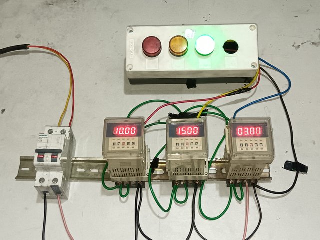
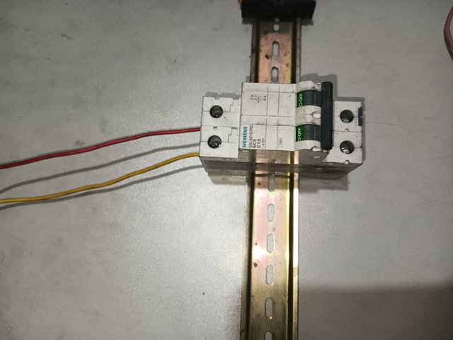
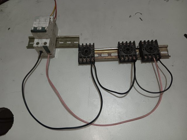
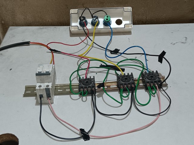
First, I will supply 220 volts to the input of the circuit breaker. Because my entire circuit will run on 220 volts.I took the red wire at the input as phase and the yellow wire as neutral.
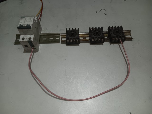
I will take the phase from the breaker's output. I will connect that phase to connector number 1 of the base of the 3rd timer. This will power my timer.
Then, I will take a black neutral wire from the breaker output and connect it to pin 1 of the base of timer number 1. From there, I will take a wire loop and connect it to pin 1 of timer number 2 and 3 bases. As a result, I will have a neutral connection in each of my timers.
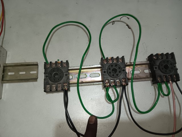
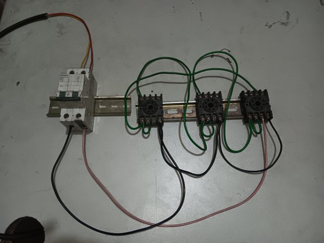
I will now take a green wire. I will short pins 7 and 8 of timer 3. I will take the green wire from pin 7 and connect it to pin 6 of timer base 2. Pin 6 is considered the normally open circuit. Similarly, I will connect timer number 2. I will do shots 7 and 8 of timer number 2. I will connect the wire from pin number 7 to pin number 6 of timer number 1.
I will now work on timer number 1. I will short its pins 7 and 8. I will connect the wire from pin 7 to pin 4 of timer number 3.
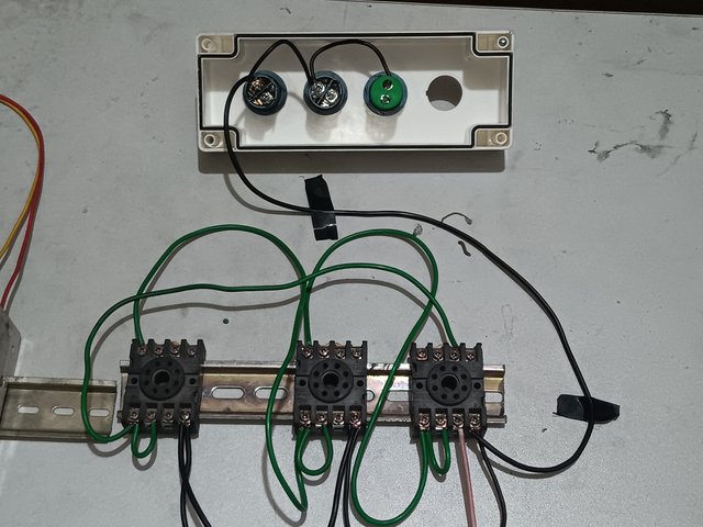
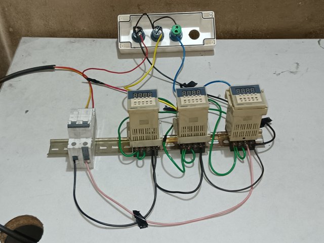
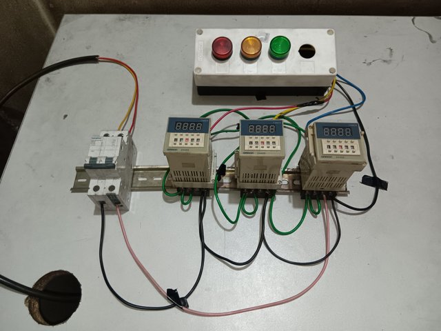
Now I will connect the timer to the indicator lamp. When my timer is on and off, the indicator lamps will turn on and off. I will take pin 1 of timer 3 as a black wire neutral and attach it to the connecting pin 1 of the indicator lamp. From there, I will take a loop and attach it to the connecting pin at one end of the other indicator lamps. This will give my indicator lamps a neutral connection.
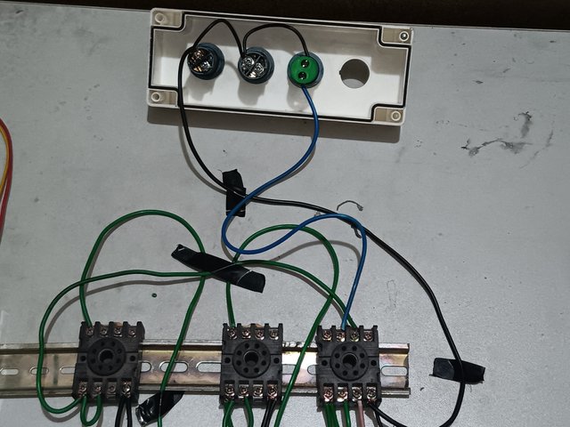 | 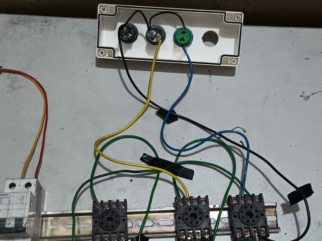 | 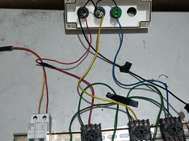 |
|---|
Now I will connect a blue wire from pin 5 of relay no. 3 to one end of the indicator lamp. In the same way, I will connect a yellow wire from pin 5 of timer no. 2 to one end of the indicator lamp. Again, I will connect a wire from pin 5 of timer no. 1 to one end of the indicator lamp.
Every timer of Pin no 5 is normally closed(NC)
Now my wiring is completely finished. I will connect the timers to the base of each timer.My base will not work properly if the timer is not connected. I will install the timer in the base by matching the base's pin number with the timer's pin number.
My entire circuit is complete. I will place the indicator lamps neatly in the control box for a good display.
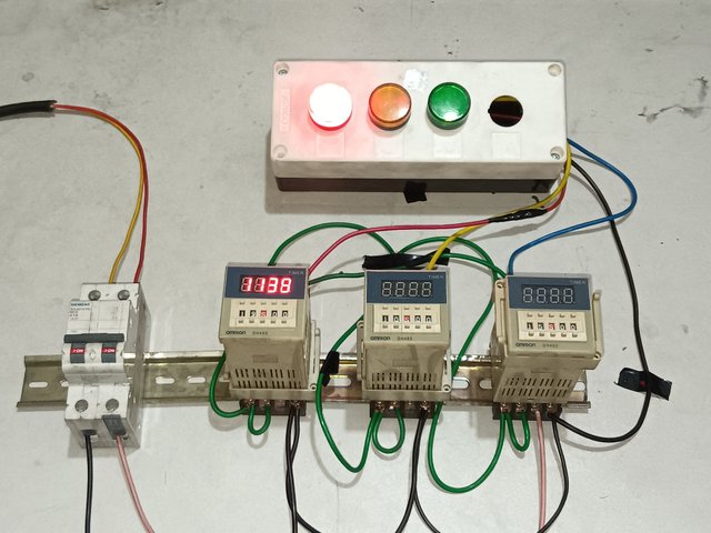
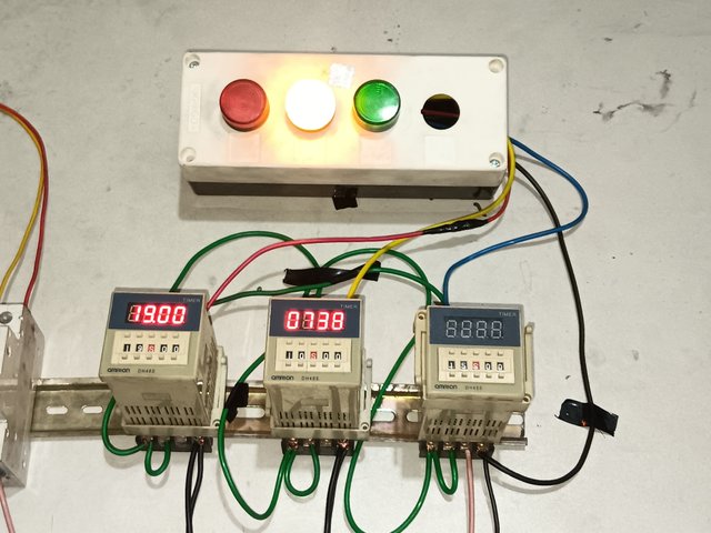
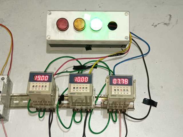
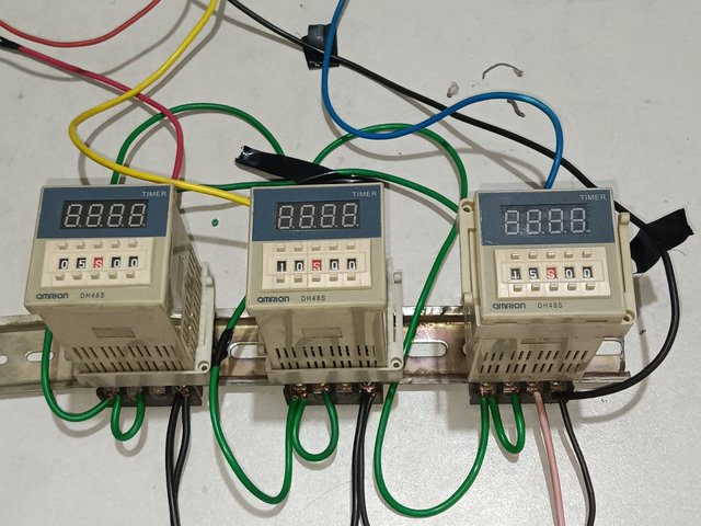
Before supplying the power, I will set the time on the timer. Both minutes and seconds can be set on the timer. So, I will set the time on the timer according to how long an indicator lamp will stay on.I set the first, second, and third timers to 5, 10, and 15 seconds respectively.
 |  |  |
|---|
I will now supply voltage to the timers. I have turned on the circuit breaker. You can see that my timers have received voltage supply. I have set the timer for the red lamp for 19 seconds. After this 19 seconds, the yellow lamp will light up. I have set the timer for the yellow lamp for 15 seconds. After the yellow lamp lights up for 15 seconds, the green lamp lights up. In the timer 3 set 10 seceond for the green light. In this way, they will automatically turn on and off after a specific time. If you want, you can set the seconds and minutes of the timer according to your time.
My job is complete. Its my YouTube link.
Thanks to everyone who read my post. I hope everyone will enjoy it.
My invitation friends
@rafi67
@azad45
@nurnobi10

Greetings sir 🫡
Waw 🫢 this is indeed a great talent which you should be proud of, once again waw 🫢 I'm really marveled by your creativity, I'm sure you are the winner of this contest already 🙏🫶 wishing you success darling 🫂
Thanks for appreciation. Pray for me to win the contest. Take care. Be happy 🤝
My pleasure sir 🫡🫂
My X promotion link
https://x.com/uddinsaif208/status/1922151253888360952?t=-WTARwcAeF_KDEvthVr8gw&s=19