Tutorial: 12 Volt DC Power Supply Circuit Connection and Battery Charger. With video tutorial.
Assalamu alaikum Everyone. I am @imranhassan From #Bangladesh
How are you all? I hope everyone is well and healthy by the grace of God. Today I will share with you a 12-volt DC power supply or charging circuit.
.png) |
|---|
In the current market, we run all the devices that have an input voltage of AC 220 volts directly, and we do not have any problems. But we have another DC voltage involved, which is from 6 volts to 12 volts, and we always see and use it through various devices, and according to our needs, we need a 6-volt or 12-volt power supply, such as for charging the battery or to run any 12-volt device directly. Today I will show you how to use a 12-volt transformer to convert it to DC and charge the battery with the output and which device can be run or used. So let's see step by step how we made our power supply or battery charging circuit.
Step -01
 |
|---|
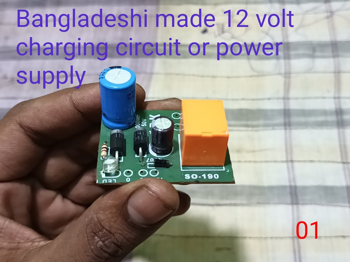
First of all, the charging circuit that you see in my hand is made by our Bangladeshis, and here two diodes, two capacitors, a relay and an indicator are given. It usually takes 12 0 12 3-ampere AC transformer input. It converts 12 volts to pure DC.
Step -02
 |
|---|
So you can see here that to start this circuit, I have taken a transformer of 220 volts AC primary and 12 volts AC secondary. There are three wires at the output of this transformer, two blue and one yellow. The yellow wire is going to 0, which means ground, and the blue wire is going to 12 volts and supplies the AC line.
Step -03
 |
|---|
Then you can see here that I have connected the three wires of the transformer to the circuit. I have given the yellow wire to ground and the two blue wires to the 12 volts AC input voltage.
Step -04
 |
|---|
There was some problem with the connection that I gave earlier. Those who designed the circuit may have made a mistake. They had connected a positive input voltage line to the ground of the circuit, due to which the capacitor got very hot. You can see it in the video. Here you can see a cross mark is given here, which is the negative line of red colour, but here the 12-volt voltage line of the transformer was given, so the negative and positive got hot together.
Then you can see my yellow ground line. I have connected it to the negative with a jumper wire through a red wire and connected it to the negative, and I have connected the two blue wires to the input voltage of the diode, and now the two positives are coming together in the capacitor of the circuit. And there is ground in the place of the round, and I have made an indicator 1 separately with resistance.
Step -05
 |
|---|
Now I have given power to the circuit, and my capacitor now has no negative-positive connection inverted. Those who designed the circuit had made a problem here, so I have done the lines nicely here, and now you can see that the power light is on where I have the light, and my circuit is now on.
Step -06
 |
|---|
Now you can see that I am checking the DC output with the help of a digital multimeter by attaching two clips. You can see that the output DC voltage on my digital meter display is above 18 volts because if there is no load here, it shows a little more with the help of the capacitor.
Step -07
 |
|---|
 |
|---|
Then I took a 12-volt motor here to check the output, and you can see that my motor is spinning very fast and the output amperage is very strong.
Step -08
 |
|---|
Then I had an old casing to enclose it, so I put the transformer there and soldered the input voltage line to the switch.
Step -09
 |
|---|
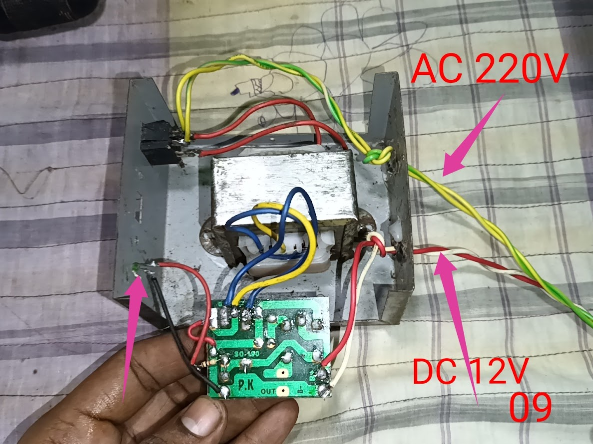
Now you can see that I have given the AC 220-volt input line to the base of the switch through the yellow and green wires. From here, the 220-volt will be switched, and after giving the 220-volt input voltage to the transformer, a line indicator has gone out as the output to show whether my circuit is on or not, and here through the white and red wires, I have taken the output line, which is 12-volt DC. This is for charging any of my 12-volt batteries and running any device.
Step -10
 |
|---|
 |
|---|
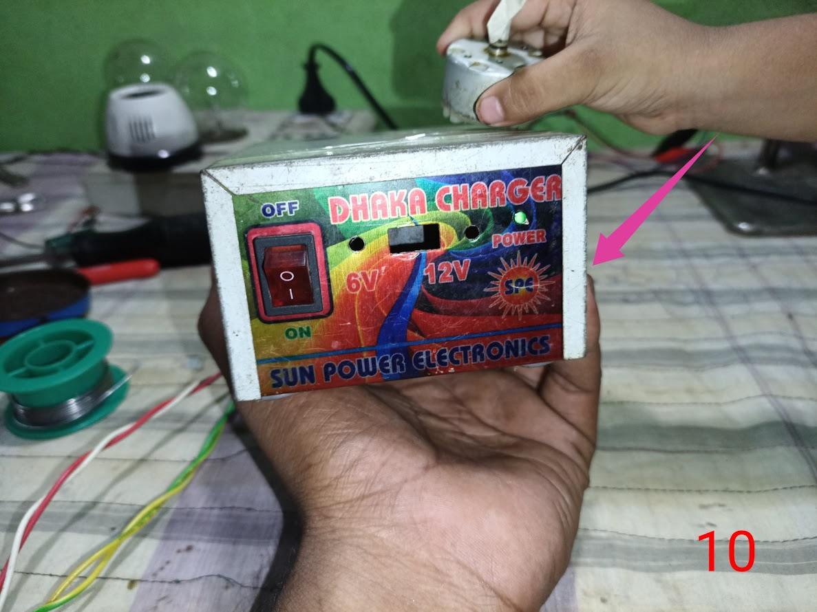
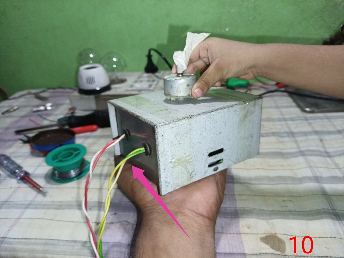
Finally, my casing is complete with body fitting, and I have a power supply with which I can do any work and charge the battery.
| In the future, I will connect an LM2596 step-down buck converter to this power supply. It can be reduced from 12 volts to 1.5 volts. |
|---|
 |
|---|
 |
|---|
In the future, I will attach a step-down converter circuit with it and use it to get a DC output from 1 volt to 12 volts to do my project work. In the future, I will bring you a tutorial post on DC voltage step-down to 12 volts. May everyone be well, God willing.
| Video Tutorial: To better understand the practical part of this tutorial, you can watch the video below. |
|---|

✅ CC: My friend @rmm31
✅ We support @pennsif and @pennsif.witness for the growth of this platform. pennsif.witness his contribution to the Steemit community. Vote for him as a Witness here: Click to Vote
| Photography Details | 📱 Device: Walton Xanon90 | 📍 Location: Narayanganj, Bangladesh | 📷 Captured By: @imranhassan |
|---|
Here is your content summary:
By improving the marked items you could get Higher Votes!
Curated by @alejos7ven
0.00 SBD,
0.10 STEEM,
0.10 SP
Thank you very much @alejos7ven sir, for giving your valuable time to my post and for supporting the post.I understand that the two cross marks in the review of my post were for the Steam promo. But I don't understand why there is a cross mark in another place. Sir, it needs to be corrected.
https://x.com/ImranHosen98536/status/1965415180332150837